Front suspension upgrade |
||
| (This is an article found on
the Internet a couple of years back - I have lost the name of the original
author. I have made corrections to this file) |
||
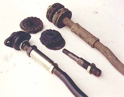
| When the factory built the SZ they devised to precisely control all suspension movements. Looking at front end, the caster rod connection to the body is a very soft rubber bushing set, (Figure 1.) Even when these are fresh, my car yielded different caster numbers on the alignment rack each time I pushed on the car. I could watch the computer screen and lean on the car and the numbers were all over the place. Just think about normal driving: you’re on and off the brakes getting ready for a corner, and then you make the turn. Meanwhile, that caster rod is moving in, out and around. | ||
|
|
||
|
Figure 1.
Even when these were fresh, my car yielded different caster numbers on the alignment rack each time I pushed on the car. I could watch the computer screen and lean on the car and the numbers were all over the place. Just think about normal driving: you’re on and off the brakes getting ready for a corner, and then you make the turn. Meanwhile, that caster rod is moving in, out and around. |
||
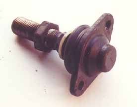
| Alfa
decided they didn’t need that action on the SZ The solution is a very
available part. It’s the caster ball/socket joint from any 105-115 series car,
(Figure 2.) This will precisely control the caster and upper arm travel. |
||
|
|
||
|
Figure 2.
As in any good repair manual: remove caster rods from you car. With parts in hand, now remove the bushing arbors, (left hand thread) from each rod and replace with the 105-115 caster joint. Use anti-seize compound on the threads, (Figure 2.) That was simple, now get out the die grinder. The hole in the body needs to be enlarged slightly for the joint to sit flat and two 8mm holes drilled for bolts to hold the joint in place, (Figure 3 & 4.) I made a cardboard template that worked well. With the new up grade in place, you will need to get an alignment done. The difference is that now whatever caster setting you have will remain that way for along time and under hard corners. |
||
|
|
||
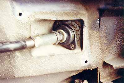
| Figure 3. After removing the caster rod and its bushings and installing the 105/115 rod-end on the caster rod, line up the new rod-end to see where body metal must be removed. Don’t remove anymore than you have to. This is not a modification that cannot be reversed without serious body work. Prior to installation, consider that you will feel more of the road through the steering wheel with this modification. |
||
|
|
||
|
Figure 4.
|
||
| Back to DIY | ||
| Check out RSRacing homepage for upgrade parts for the caster rod end | ||