|
TS engine tuning project |
|||||
|
Under construction... |
|
...and under consideration | |||
| Having now two 2 liter TS
engines, I have the opportunity to work on one while the other is installed
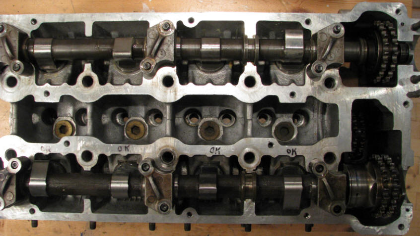
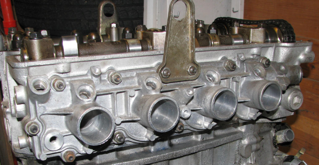
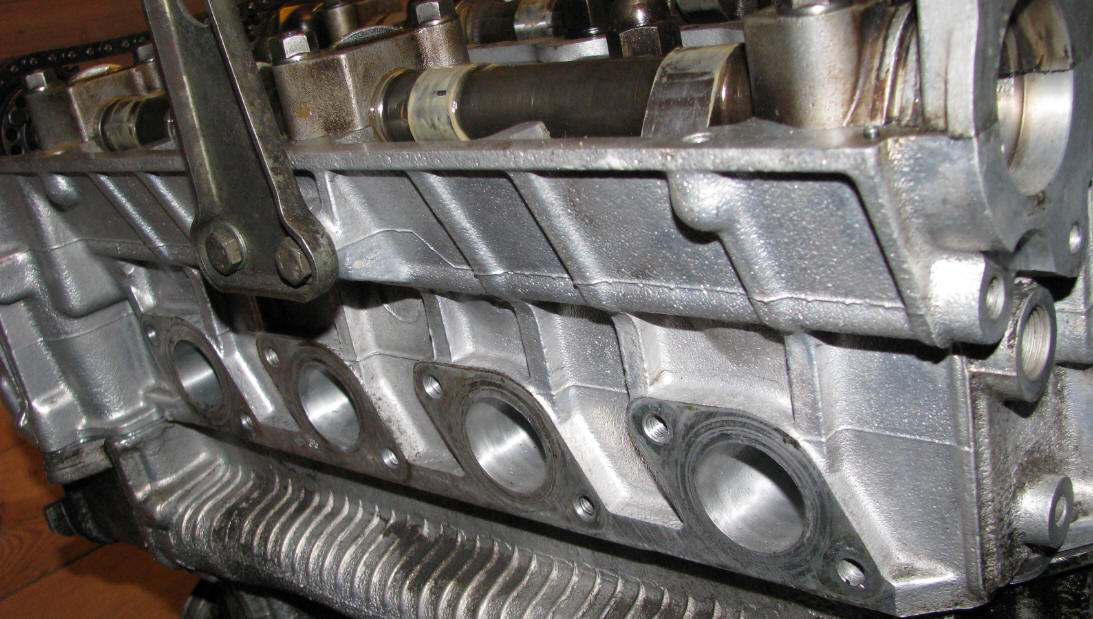
in my car. Therefore I want to do some tuning to my extra engine, based on the "The DOHC Engine High Performance manual" by Jim Kartalamakis as well as ideas from my own Alfa Romeo network and friends here in DK. The "new" TS engine was acquired by mid 2010, and has supposedly around 70 - 80.000 km's on the clock, I have no chance of telling as the engine was removed from the car prior to I picked it up. I plan to dismantle the engine quite a bit to make sure it is safe and sound for proper tuning. The engine has had its exhaust cam shaft replaced (with a new stock, I have decided to keep cost low and will not replace the cams with high lift cams) and the cylinder head has been grinded at a workshop to increase compression ratio and to make sure it will not blow the head gasket once I make the engine really work. |
|||||
  |
|||||
 |
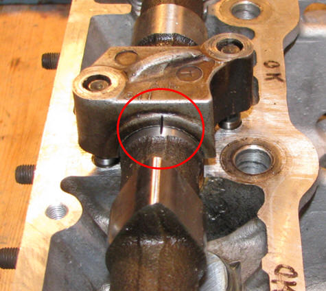
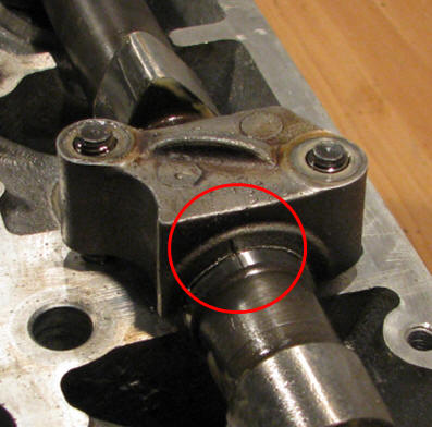
Note
the position of the cam by the mark in the camshaft as well as the upper
bearing housing, there is a identical set of marks on the other cam shaft as
well as on the V-belt driven. When these three marks are all in aligned you have a good starting point for aligning the pistons and valves. |
||||
| As mentioned, this should be used for initial installation - there can be huge difference between the optimum place. You NEED to measure the right positions. I will add more details once I know how to do it right | |||||
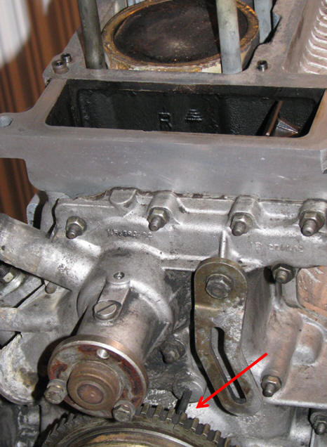
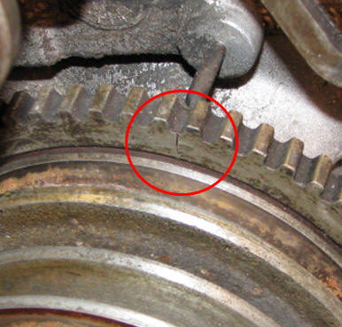
Note the position of piston number one. This is at Top Dead Center (TDC) and the mark in the crankshaft pulley is aligned. |
 |
 |
 |
||
| Nice and almost clean | Nice and clean | ||||
 |
|
||||
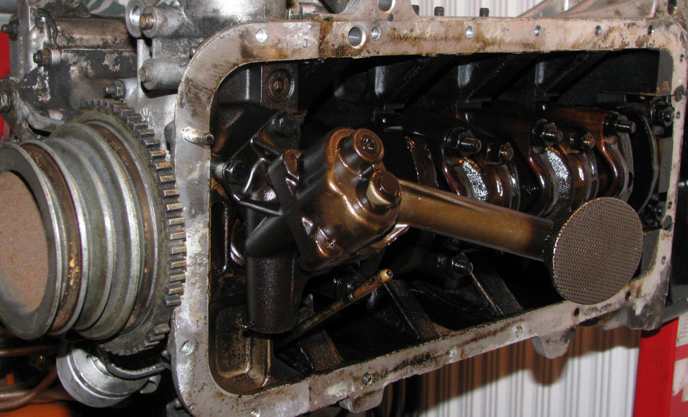 |
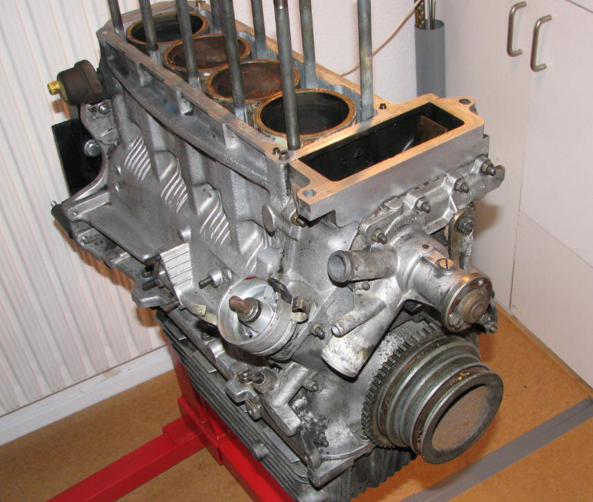
Need to do some cleaning of the flanges for
the oilpan, otherwise it looks quite fine. I will perform a thorough
inspection of all parts, and will partly assemble the engine to make sure,
that everything is in perfect working order. First I need to check the slack for the two chains driving the cam shafts. Also the packing at the outlet shaft of the the engine will get a fresh packing, to make sure it doesn't leak once it is installed in my car. Of cause all pistons and pistons rod will be removed and checked. The cylinder lining looks VERY nice! |
||||
| "Plan of attack" | |||||
| Part of engine | Modification | Purpose | How to do | Risk | |
| Cylinder head | Flowing inlet ports | Increase air flow = more torque and horse power |
Grinding and sanding ports, floor and walls (not "roof"!) | Removing to much materiel will puncture the wall to the water cooling | |
| Cylinder head | Flowing outlet ports | Increase air flow = more torque and horse power |
Grinding and sanding ports, floor and walls (not "roof"!) | Removing to much materiel will puncture the wall to the water cooling | |
| Cylinder head | Flange lowered | Increase compression and make sure the flange is 100 % straight and tight | This is a job for a professional workshop with appropriate tools | workshop grinder is not 100 % straight and will make more damage than good | |
| Combustion chamber |
Combustion chamber volume matching.
All match at 44 ml. |
Enable engine to be fully loaded on all cylinders without risk of one of them to hammering and obtain even torque | With the use of a syringe, a piece of Plexiglas, water and a small grinder. read the rest in the book by Jim Kartalamakis | Removing too much material, and you're back to square one... | |
Piston rods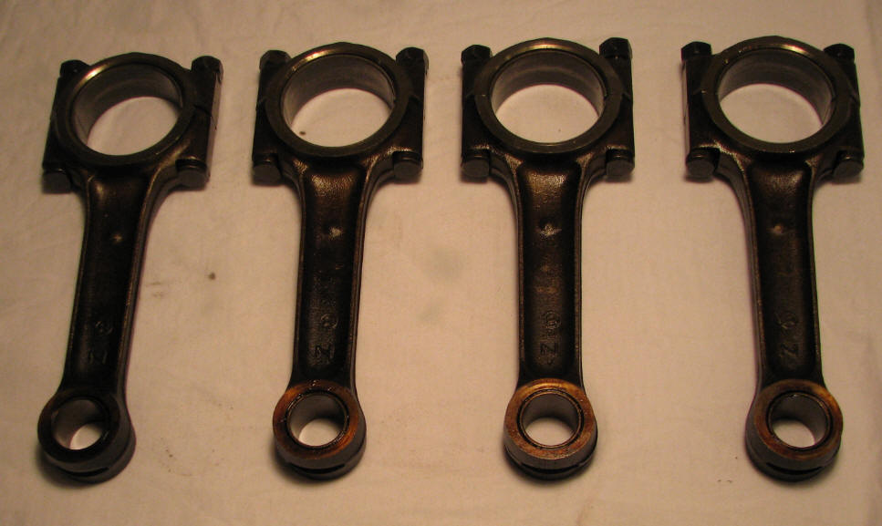 |
Lightening and "lengthening" | Piston rods removed from my original Alfetta QO engine. These rods are 1 mm longer than the rods from the TS engine giving an additional increase of 1 - 1½ in compression ration (CR). | Simply replace the stock TS piston rods with a set from and old Nord engine after "cleaning" of excess material | ||
| Balancing | Reduce vibrations in engine | A fine weight and a small air grinder | Carefully! | ||
| Nicely grinded Nord engine piston rods, I have removed approx. 20 g per set. |
 |
||||
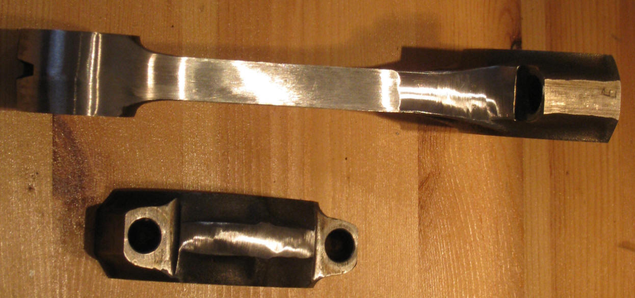
| You can barely notice the 1 mm additional lift of the piston to the right (cylinder 3) compared to the piston with the standard piston rod shown to the left (cylinder 2). This should raise the compression ration from approx. 10 to 11 - 11½. |
 |
||||
| Engine block | Cleaning | ||||
| Flywheel | Lightening | Faster response on engine revs | Imbalance in drive train (prop shaft and clutch) | ||
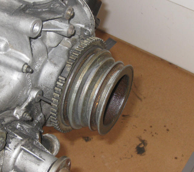
| Crank pulley | Lightening, by removing two unused pulleys (Aircon and power steering) | Little faster response on engine revs, probably more on the theoretic basis than on the practical... | Remove two unused pulley tracks and maybe some material on the inside of the pulley (approx. 0.6 kg gone) | Imbalance in drive train (prop shaft and clutch) | |
 |
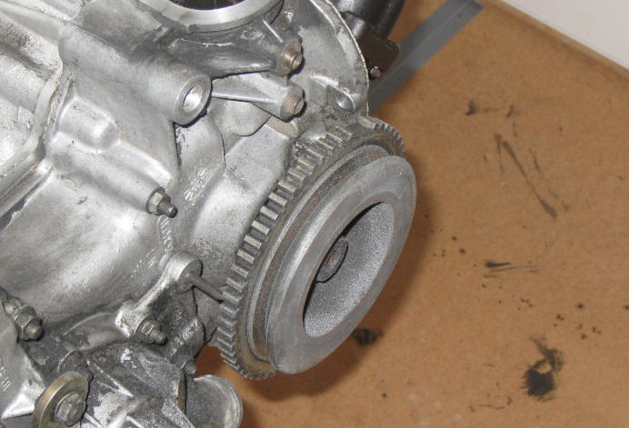 |
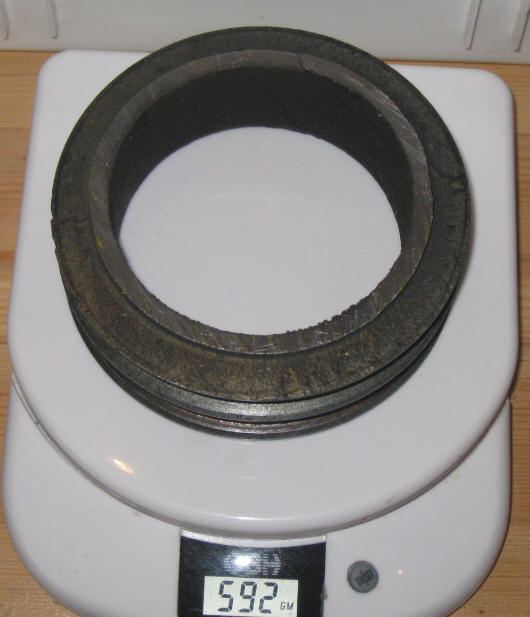 |
|||
| Intake | K&N filter installed | Make sure there is absolutely no restrictions in the intake system | Remove old filter and install K&N filter - this might require that you support the air measure valve | ||
| Intake manifold | Rework the existing manifold, and replace the four inlet tubes with straight and larger inside diameter aluminum tubing for better flow. | Increase air flow = more torque and horse power |
Saw off the four bended inlet tubes and weld on straight tubes, this will require that I lower the entire inlet. | ||
| Wok on modifying the intake manifold has commenced |
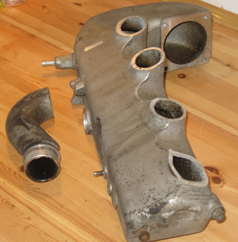 |
||||
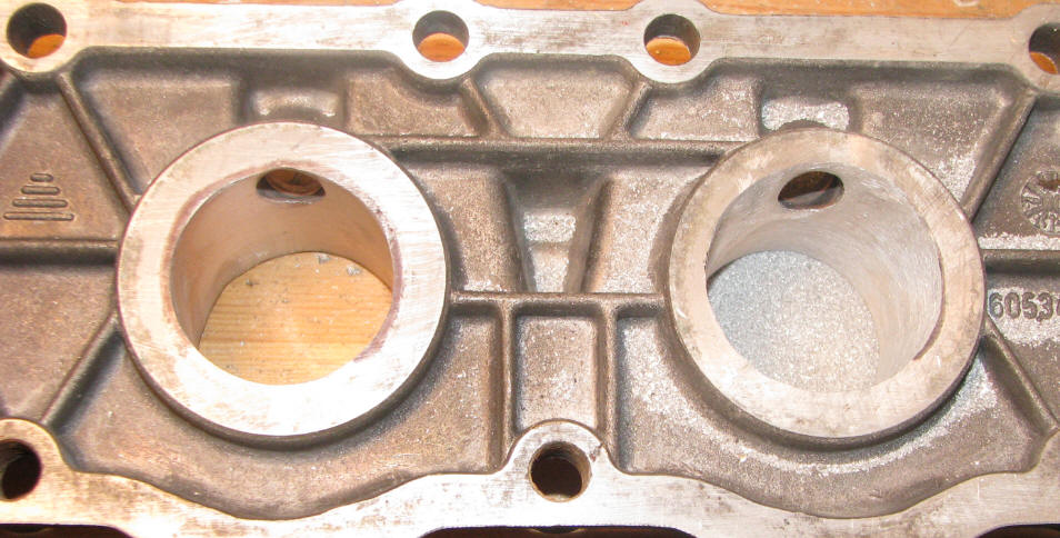
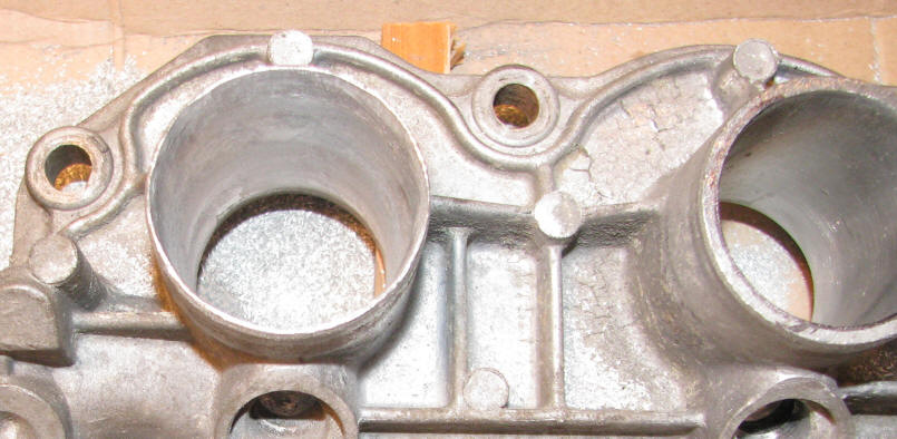
| Note
the difference in wall thickness of the two inlet ports. Diameter is increased from 39 mm to 41 mm, which corresponds to 10 % larger area. Increasing the flow area of these ports is a 6 hour job - I hope it pays of! |
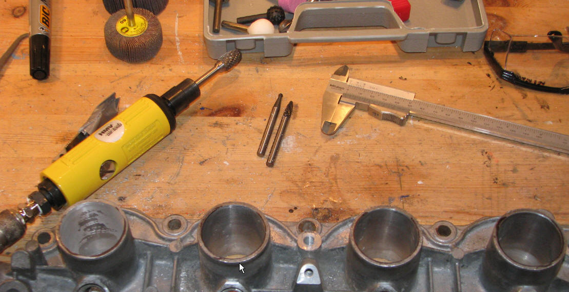 |
||||
| The picture to the left is from the back side which has more material the on the front. |
 |
 |
|||
| Exhaust | CSC exhaust manifold installed | Increase horse power and torque as the engine better can get the exhaust gases out | |||
| Add asbestos wrapping to manifold | Keep temperature high in the exhaust to increase flow - lower temperature in engine bay | ||||
| Fuel pump | Increased voltage to 13 - 14 Volt, by installing a new 4 mm2 wire and adding a 12V relay powered by the original wire for the fuel pump | Make sure that that is sufficient volume and fuel pressure for better atomization of the fuel in the combustion chamber |
Risk is loss of time and money, as the regulator on the fuel line might have
a lower pressure setting. Fuel pump wears out as it received 14+ Volt instead of 9.5 Volts... |
||
| Fuel injectors | New 5 port fuel injectors installed | Theoretically a better "mist" and maybe better capacity? | Remove the old - install the new | No risk | |
| Ignition | |||||
| Engine management | |||||
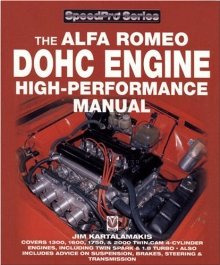 |
As reference for many of the modifications I have heavily depended on this great book by Jim Kartalamakis | Do it right the first time | If you consider to do any serious engine tuning this is THE book to buy. Find it on e.g. Amazon.com | You will never get the tuning done - but has spent many hours dreaming | |
| Note
the difference in wall thickness of the two inlet ports. Diameter is increased from 39 mm to 41 mm, which corresponds to 10 % larger area. Increasing the flow area of these ports is a 6 hour job - I hope it pays of! |
 |
||||
| Before and after |
 |
 |
|||
| Back to DIY | |||||
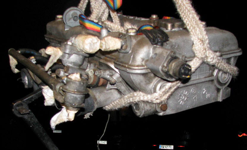
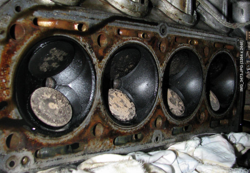
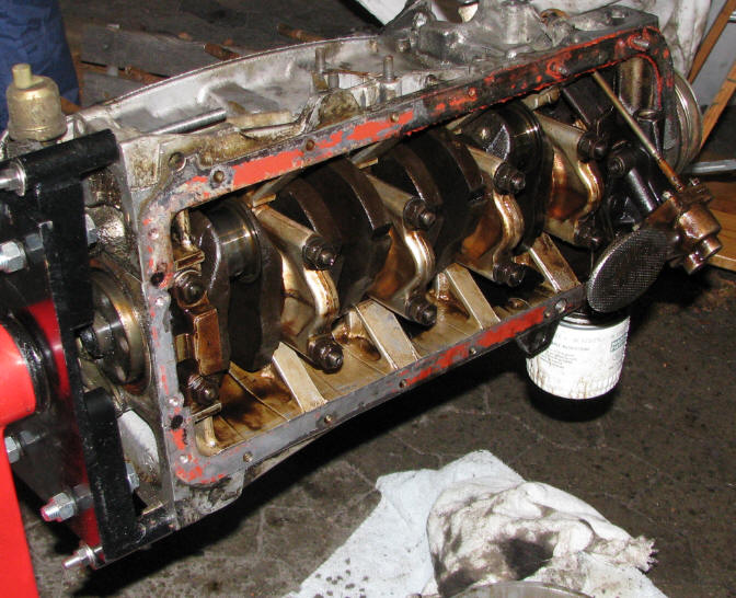
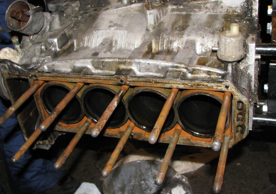
| Below is pictures from when we dismantled the original "Nord" engine from the Alfetta, in order to get to the piston rods as I need those for TS tuning project. | |||||
| We had to lift the entire engine in order to use gravity to pull the engine block away from the cylinder head, besides carefully using a hammer and a crowbar, it took about 1 hour. | This
is what a 160.000 km head looks like on the inside - not too bad. The residue is probably caused by oil in the combustion chamber |
||||
 |
 |
||||
| The crankshaft - pistons rod and everything looked to be in a very good condition | Taking the pistons out revealed only little scraping on the intake side of the pistons and there was still clears marks inside the cylinder sleeve from the final high grit grinding. | ||||
 |
 |
||||
